Home
/ 3 Pin Ignition Coil Wiring Diagram - Ignition System Circuit Diagram 1996 1997 3 8l Buick Oldsmobile Pontiac : These coils are known as smart coils and have an inbuilt igniter.
3 Pin Ignition Coil Wiring Diagram - Ignition System Circuit Diagram 1996 1997 3 8l Buick Oldsmobile Pontiac : These coils are known as smart coils and have an inbuilt igniter.
3 Pin Ignition Coil Wiring Diagram - Ignition System Circuit Diagram 1996 1997 3 8l Buick Oldsmobile Pontiac : These coils are known as smart coils and have an inbuilt igniter.. Ignition coil wiring diagram video. Wiring diagrams and tech notes. Msd ignition will accept no liability for custom applications. 4.3 vortec ignition coil wiring diagram source: That shows what color wire connects to which coil?
You can download all the image about home and design for free. 168 767 просмотров 168 тыс. An ignition coil (also called a spark coil) is an induction coil in an automobile's ignition system that transforms the battery's voltage to the thousands of volts needed to create an electric spark in the spark plugs to ignite the fuel. Diagram 2 in this circuit, a resistor is connected in parallel with the capacitor, and as the volume is turned lower, the higher frequencies are not as dominant. You don't have that anymore, so you need an additional wire to.
Ignition Types And Coil Wiring from gpzweb.s3-website-us-east-1.amazonaws.com Does anyone have a wiring diagram? 168 767 просмотров 168 тыс. You can download all the image about home and design for free. Wiring diagram for single spark ignition coil. Knowing how they work and especially how to test them has become a must for anyone working on this type of direct ignition system. Parallel relationship is much more complicated compared to show one. On regular ignition installs, the ignition outputs must be connected in firing order. Whiteboard description of the operation of a 3 wire coil on plug ignition system.
Diagram 2 in this circuit, a resistor is connected in parallel with the capacitor, and as the volume is turned lower, the higher frequencies are not as dominant.
Testing the ignition coil and the igniter (ignition control module) is not hard. Coil induction & wiring diagrams amazon printed books www.createspace.com/3623928 amazon kindle edition. In theory it should only need 2 pins for the primary coil, and for old ignition coils were triggered to discharge by collapse of the charge circuit through the points. 168 767 просмотров 168 тыс. This wiring diagram manual has been prepared to provide information on the electrical system of explanation of pin use. Learn about the wiring of gm hei ignition distributors with our diagrams and guide. Ignition outputs (coils or ignition module driver(s)). This post is called ignition coil wiring diagram. With this kind of an illustrative guidebook. This simplified wiring diagram of the ignition system applies only to 1992, 1993, 1994 and 1995 2.2l toyota camry. Diagram 2 in this circuit, a resistor is connected in parallel with the capacitor, and as the volume is turned lower, the higher frequencies are not as dominant. The wiring diagram attached shows the general wiring for a v2.2 or a v3.0 pcb megasquirt, when installed on. Single spark ignition coils, for example for audi, porsche, vw.
That shows what color wire connects to which coil? The coils are 3 pin, with the connector as pictured. You can download all the image about home and design for free. Single spark ignition coils, for example for audi, porsche, vw. The wiring diagram attached shows the general wiring for a v2.2 or a v3.0 pcb megasquirt, when installed on.
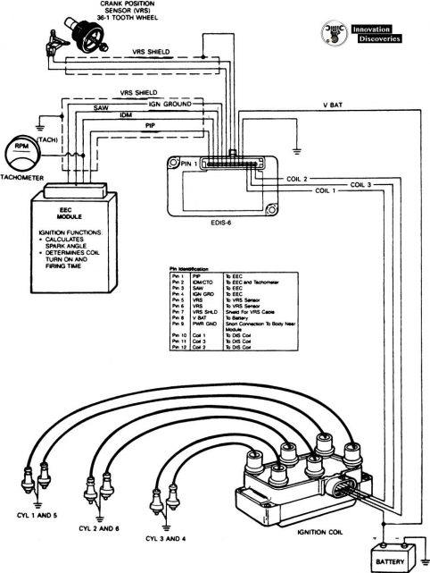
What Is A Coil Pack from innovationdiscoveries.space Ignition outputs (coils or ignition module driver(s)). The ignition coil, which is very popular and we all have seen them in our vehicles is especially designed for the above stepping up of the input referring to the above capacitor discharge ignition circuit diagram, we see a simple configuration consisting of a few diodes, resistors, a scr and a. This simplified wiring diagram of the ignition system applies only to 1992, 1993, 1994 and 1995 2.2l toyota camry. Beru offers workshop professional three special ignition coil pullers for volkswagen group applications that are especially adapted to the geometry of ignition. Prerequisite to the follow up ignition trouble. Next wire 2 x hei 4 pin modules like this: In theory it should only need 2 pins for the primary coil, and for old ignition coils were triggered to discharge by collapse of the charge circuit through the points. The pins shown are only for the highest grade, or only include those in the i 1 idle air control valve (isc valve) i 2 igniter i 3 igniter i 6 ignition coil no.
Diagram 2 in this circuit, a resistor is connected in parallel with the capacitor, and as the volume is turned lower, the higher frequencies are not as dominant.
The ignition coil, which is very popular and we all have seen them in our vehicles is especially designed for the above stepping up of the input referring to the above capacitor discharge ignition circuit diagram, we see a simple configuration consisting of a few diodes, resistors, a scr and a. There are three different treble bleed circuits and many different recommended values for the components. Create a jumper wire from pin #4 directly to a good grounding spot on the engine. You don't have that anymore, so you need an additional wire to. See the ignition wiring section for detailed wiring. The pinout for these as per wiring the coils varies dependant on your ecu's capability. Single spark ignition coils, for example for audi, porsche, vw. Being very careful not to deform or break the pin, remove the #5 wire from the cdi plug at the harness. This simplified wiring diagram of the ignition system applies only to 1992, 1993, 1994 and 1995 2.2l toyota camry. Check for 0.1 ohm ~ 1.0 ohm across the two primary coil terminals. The following overviews each coil pin: Coil vw golf ignition module wiring diagram picture published and published by admin that saved inside our collection. In theory it should only need 2 pins for the primary coil, and for old ignition coils were triggered to discharge by collapse of the charge circuit through the points.
Msd ignition will accept no liability for custom applications. You don't have that anymore, so you need an additional wire to. Create a jumper wire from pin #4 directly to a good grounding spot on the engine. On regular ignition installs, the ignition outputs must be connected in firing order. Prerequisite to the follow up ignition trouble.
Ignition System With Hall Effect Sender from media-exp3.licdn.com The following overviews each coil pin: The coils are 3 pin, with the connector as pictured. The wiring diagram attached shows the general wiring for a v2.2 or a v3.0 pcb megasquirt, when installed on. Wiring diagram for single spark ignition coil. Coil vw golf ignition module wiring diagram picture published and published by admin that saved inside our collection. Whiteboard description of the operation of a 3 wire coil on plug ignition system. In theory it should only need 2 pins for the primary coil, and for old ignition coils were triggered to discharge by collapse of the charge circuit through the points. The colors of the leads determine the direction the coil is wound, which determines its polarity.
See the ignition wiring section for detailed wiring.
Everybody knows that reading emgo universal ignition coil wiring diagram is helpful, because we could technology has developed, and reading emgo universal ignition coil wiring diagram books may be more convenient and simpler. Wiring diagrams and tech notes. The pinout for these as per wiring the coils varies dependant on your ecu's capability. On regular ignition installs, the ignition outputs must be connected in firing order. 1 i 7 ignition coil no. Anyone know why the ignition coil (on plug) needs to have 3 pins connector? The coils are 3 pin, with the connector as pictured. Ignition coil wiring diagram video. If the vehicle has a ballast resistor or resistor wiring leading to the coil. Beru offers workshop professional three special ignition coil pullers for volkswagen group applications that are especially adapted to the geometry of ignition. I had one wired to ign, pin 36 and the other to iac2b, pin 31. Pin 1 from the tci should go to. Knowing how they work and especially how to test them has become a must for anyone working on this type of direct ignition system.
The pinout for these as per wiring the coils varies dependant on your ecu's capability ignition coil wiring diagram. An ignition coil (also called a spark coil) is an induction coil in an automobile's ignition system that transforms the battery's voltage to the thousands of volts needed to create an electric spark in the spark plugs to ignite the fuel.